RIE 2 (MRC): Difference between revisions
No edit summary |
(added SOP section) |
||
| Line 11: | Line 11: | ||
|toolid=25 |
|toolid=25 |
||
}} |
}} |
||
= |
==About== |
||
| Line 18: | Line 18: | ||
RIE of InP and related compounds can be achieved with a hydride-based process chemistry of methane/hydrogen with an etching mechanism due to a "reverse" metalorganic CVD reaction. Because both etching and deposition occur simultaneously, it is important to use the proper gas flows and to periodically remove any polymer reaction by-products deposited on the non-etched (mask) surfaces. (This system has an additional flow circuit in order to bleed in small amounts, <1 sccm, of O<sub>2</sub>). Alternatively, one can perform cyclic etching between MHA and O<sub>2</sub> to keep polymer formation to a minimum. With this technique selectivity is quite high and anisotropic etching can be achieved. While a metal, dielectric or photoresist may be used as a mask, photoresist should only be used at low bias voltages in order to avoid mask pattern distortions due to reflow. A precoat etch should be done before etching to condition the chamber. |
RIE of InP and related compounds can be achieved with a hydride-based process chemistry of methane/hydrogen with an etching mechanism due to a "reverse" metalorganic CVD reaction. Because both etching and deposition occur simultaneously, it is important to use the proper gas flows and to periodically remove any polymer reaction by-products deposited on the non-etched (mask) surfaces. (This system has an additional flow circuit in order to bleed in small amounts, <1 sccm, of O<sub>2</sub>). Alternatively, one can perform cyclic etching between MHA and O<sub>2</sub> to keep polymer formation to a minimum. With this technique selectivity is quite high and anisotropic etching can be achieved. While a metal, dielectric or photoresist may be used as a mask, photoresist should only be used at low bias voltages in order to avoid mask pattern distortions due to reflow. A precoat etch should be done before etching to condition the chamber. |
||
= |
==Detailed Specifications== |
||
*Etch gases include: CH<sub>4</sub>, H<sub>2</sub>, Ar and O<sub>2</sub> |
*Etch gases include: CH<sub>4</sub>, H<sub>2</sub>, Ar and O<sub>2</sub> |
||
*Low 1 E -6 ultimate chamber pressure |
*Low 1 E -6 ultimate chamber pressure |
||
*13.56 Mhz excitation frequency |
*13.56 Mhz excitation frequency |
||
*Sample size limited to approximately 2 inches |
*Sample size limited to approximately 2 inches |
||
*HeNe and IR laser monitoring for endpoint |
*HeNe and IR laser monitoring for endpoint |
||
*Automatic tuning network |
*Automatic tuning network |
||
*DC Bias or RF power control |
*DC Bias or RF power control |
||
*Masking materials include: Ni, SiON, photoresist (limited to low bias/power) |
*Masking materials include: Ni, SiON, photoresist (limited to low bias/power) |
||
*Typical etch conditions for InGaAsP: |
*Typical etch conditions for InGaAsP: |
||
**75 mT (CH<sub>4</sub>/H<sub>2</sub>/Ar : 4/20/10 sccm) |
**75 mT (CH<sub>4</sub>/H<sub>2</sub>/Ar : 4/20/10 sccm) |
||
**450v bias |
**450v bias |
||
**~ 45 nm/min. etch rate |
**~ 45 nm/min. etch rate |
||
== Procedures == |
|||
RIE #2 Standard Operating Procedure |
|||
Revision as of 22:01, 11 September 2019
| |||||||||||||||||||||
About
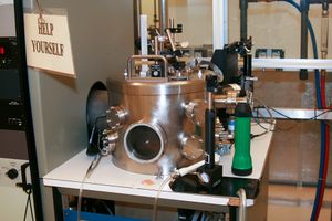
This is a Materials Research Corporation RIE-51 parallel plate, 13.56 Mhz system used primarily for the etching of InP with CH4/H2/Ar gases, although it can be used to etch As- and Sb-based III-V compounds and a variety of II-VI semiconductors as well. For Al-containing compounds and II-VI compounds, high bias power is required. Tool features include: six inch diameter water cooled cathode/substrate platform, pyrex cylinder for plasma confinement and gas flow control, adjustable cathode-anode spacing, fixed bias or power control and HeNe laser etch monitor with chart recorder. It is diffusion pumped and has no loadlock. Various etching applications have included: in-plane lasers/facets, InP-based HBTs, FET gate recessing, InP-based quantum microcavities, Bragg-Fresnel x-ray lenses and waveguides.
RIE of InP and related compounds can be achieved with a hydride-based process chemistry of methane/hydrogen with an etching mechanism due to a "reverse" metalorganic CVD reaction. Because both etching and deposition occur simultaneously, it is important to use the proper gas flows and to periodically remove any polymer reaction by-products deposited on the non-etched (mask) surfaces. (This system has an additional flow circuit in order to bleed in small amounts, <1 sccm, of O2). Alternatively, one can perform cyclic etching between MHA and O2 to keep polymer formation to a minimum. With this technique selectivity is quite high and anisotropic etching can be achieved. While a metal, dielectric or photoresist may be used as a mask, photoresist should only be used at low bias voltages in order to avoid mask pattern distortions due to reflow. A precoat etch should be done before etching to condition the chamber.
Detailed Specifications
- Etch gases include: CH4, H2, Ar and O2
- Low 1 E -6 ultimate chamber pressure
- 13.56 Mhz excitation frequency
- Sample size limited to approximately 2 inches
- HeNe and IR laser monitoring for endpoint
- Automatic tuning network
- DC Bias or RF power control
- Masking materials include: Ni, SiON, photoresist (limited to low bias/power)
- Typical etch conditions for InGaAsP:
- 75 mT (CH4/H2/Ar : 4/20/10 sccm)
- 450v bias
- ~ 45 nm/min. etch rate
Procedures
RIE #2 Standard Operating Procedure
