Filmetrics F40-UV Quick Start: Difference between revisions
Jump to navigation
Jump to search
(moved images to in-line) |
|||
| Line 2: | Line 2: | ||
Microscope-mounted Optical Thin-Film Analyzer |
Microscope-mounted Optical Thin-Film Analyzer |
||
=== Startup and Calibration === |
=== Startup and Calibration === |
||
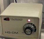
# Turn on light source to about 12 o'clock |
# Turn on light source to about 12 o'clock |
||
## Optionally wait |
## Optionally wait 1 min for light intensity to stabilize.[[File:Filmetrics F40-UV - light source setting 02.jpg|thumb|150x150px|Set the light source to 12 o'clock|none]] |
||
# Open Software "'''FILMeasure'''". Activate "'''Live Video'''" Tab. |
# Open Software "'''FILMeasure'''". Activate "'''Live Video'''" Tab. |
||
# Load "Filmetrics Focus/Reference Wafer" onto stage, avoiding hole [[File:Filmetrics F40-UV - wafer placement 03.jpg|thumb|200x200px|Approximate placement of a 4-inch wafer]] |
# Load "Filmetrics Focus/Reference Wafer" onto stage, avoiding hole [[File:Filmetrics F40-UV - wafer placement 03.jpg|thumb|200x200px|Approximate placement of a 4-inch wafer|none]] |
||
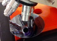
# Rotate uScope turret to desired microscope objective |
# Rotate uScope turret to desired microscope objective |
||
# Focus on wafer - use edge of blue (SiO2) features |
# Focus on wafer - use edge of blue (SiO2) features |
||
# In "'''Live Video'''" tab, make sure wafer is in focus, and black spot (measurement region) is on grey Silicon region only. |
# In "'''Live Video'''" tab, make sure wafer is in focus, and black spot (measurement region) is on grey Silicon region only.[[File:Filmetrics F40-UV - focus on bare silicon 04.jpg|thumb|200x200px|Focus on the bare silicon in the FILMeasure software, for Si Reference scan|alt="Live Video" tab showing focused wafer|none]] |
||
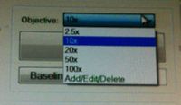
# Set software to use appropriate Objective calibration from dropdown list, eg. "10x" |
# Set software to use appropriate Objective calibration from dropdown list, eg. "10x"[[File:Filmetrics F40-UV - objective choice 05.jpg|thumb|200x200px|Choose objective calibration in software|none]] |
||
# Click '''[Baseline…]''', set to "'''Si'''" and '''[Take Reflectance Standard]''' & '''[Next-->]''' |
# Click '''[Baseline…]''', set to "'''Si'''" and '''[Take Reflectance Standard]''' & '''[Next-->]''' |
||
## If a warning about intensity change pops up, ignore it and hit '''[OK]''' |
## If a warning about intensity change pops up, ignore it and hit '''[OK]''' |
||
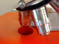
# Move stage so microscope shoots through hole in stage |
# Move stage so microscope shoots through hole in stage |
||
| ⚫ | |||
# Click '''[Take Background]''' & '''[Finish]''' |
|||
{| |
|||
![[File:Filmetrics F40-UV - focus on bare silicon 04.jpg|thumb|200x200px|Focus on the bare silicon in the FILMeasure software, for Si Reference scan|alt="Live Video" tab showing focused wafer]] |
|||
![[File:Filmetrics F40-UV - objective choice 05.jpg|thumb|200x200px|Choose objective calibration in software]] |
|||
| ⚫ | |||
|} |
|||
=== Sample Measurement === |
=== Sample Measurement === |
||
# Focus on your sample/feature of interest & place the black aperture spot on the measurement region. Here we will measure the SiO<sub>2</sub> on the Filmetrics Reference Wafer. |
# Focus on your sample/feature of interest & place the black aperture spot on the measurement region. Here we will measure the SiO<sub>2</sub> on the Filmetrics Reference Wafer. |
||
| Line 25: | Line 19: | ||
# Select a recipe from the Dropdown list (ok to ''discard changes''), and Click '''[Edit Recipe…]''' to set the layers to approximately what you expect to measure. |
# Select a recipe from the Dropdown list (ok to ''discard changes''), and Click '''[Edit Recipe…]''' to set the layers to approximately what you expect to measure. |
||
## Enable the checkbox next to the thicknesses you want it to measure/calculate, and Disable checkboxes next to any values you want the software to use pre-programmed values for. |
## Enable the checkbox next to the thicknesses you want it to measure/calculate, and Disable checkboxes next to any values you want the software to use pre-programmed values for. |
||
## Optionally enable the check box next to n & k - but only if you know what refractive index and extinction you expect. If you don't know these values, Disable the "Meas" checkbox for n & k. When enabled, you'll want to make sure the calculated refractive index (n) is close to the expected value. |
## Optionally enable the check box next to '''n''' & '''k''' - but only if you know what refractive index and extinction you expect. If you don't know these values, Disable the "Meas" checkbox for n & k. When enabled, you'll want to make sure the calculated refractive index (n) is close to the expected value. |
||
# '''Re-Select the correct microscope objective''' & Click '''[Measure]''' |
# '''Re-Select the correct microscope objective''' & Click '''[Measure]''' |
||
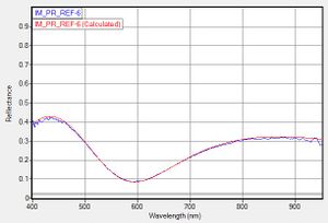
# Make sure the blue (measured) and red (calc'd) curves have reasonably good agreement. Goodness of fit >90% is pretty good. Refractive Index (n), if calc'd, should be near the expected value for the film. |
# Make sure the blue (measured) and red (calc'd) curves have reasonably good agreement. Goodness of fit >90% is pretty good. Refractive Index (n), if calc'd, should be near the expected value for the film. |
||
Revision as of 05:55, 5 September 2018
Demis D. John, UCSB NanoFab, Updated: 2018-07-17
Microscope-mounted Optical Thin-Film Analyzer
Startup and Calibration
- Turn on light source to about 12 o'clock
- Optionally wait 1 min for light intensity to stabilize.
- Open Software "FILMeasure". Activate "Live Video" Tab.
- Load "Filmetrics Focus/Reference Wafer" onto stage, avoiding hole
- Rotate uScope turret to desired microscope objective
- Focus on wafer - use edge of blue (SiO2) features
- In "Live Video" tab, make sure wafer is in focus, and black spot (measurement region) is on grey Silicon region only.
- Set software to use appropriate Objective calibration from dropdown list, eg. "10x"
- Click [Baseline…], set to "Si" and [Take Reflectance Standard] & [Next-->]
- If a warning about intensity change pops up, ignore it and hit [OK]
- Move stage so microscope shoots through hole in stage
- Click [Take Background] & [Finish]
Sample Measurement
- Focus on your sample/feature of interest & place the black aperture spot on the measurement region. Here we will measure the SiO2 on the Filmetrics Reference Wafer.
- It is ok to change the objective, just make sure the same calibrated objective is chosen before measuring.
- Select a recipe from the Dropdown list (ok to discard changes), and Click [Edit Recipe…] to set the layers to approximately what you expect to measure.
- Enable the checkbox next to the thicknesses you want it to measure/calculate, and Disable checkboxes next to any values you want the software to use pre-programmed values for.
- Optionally enable the check box next to n & k - but only if you know what refractive index and extinction you expect. If you don't know these values, Disable the "Meas" checkbox for n & k. When enabled, you'll want to make sure the calculated refractive index (n) is close to the expected value.
- Re-Select the correct microscope objective & Click [Measure]
- Make sure the blue (measured) and red (calc'd) curves have reasonably good agreement. Goodness of fit >90% is pretty good. Refractive Index (n), if calc'd, should be near the expected value for the film.
- If fit is bad (low GoF) or refractive index is far off, this measurement is inaccurate. If Red curve is much too wavy or too smooth, then your guess of thickness was not close enough - [Edit Recipe] & [Analyze] again until you get a good fit.
ShutDown
- Set objective to 10x & Remove Sample
- TURN OFF THE LIGHT SOURCE
- The halogen light source does die eventually, so prolong the life by turning off when not in use.
- If doing repeated measurements, leave a note with date/time.
