UCSB NanoFab Microscope Training: Difference between revisions
m →Overview: minor addition/format |
→Bright/Dark Field Explanation: added example DF image, explanation image, and DIC example image |
||
| (19 intermediate revisions by 2 users not shown) | |||
| Line 1: | Line 1: | ||
== |
==Overview== |
||
We have numerous optical microscopes in our lab, each of which is a different model or manufacturer. |
We have numerous optical microscopes in our lab, each of which is a different model or manufacturer. |
||
However, almost all of these microscopes share common features, even if the knob to enable the feature is in a different location. This "training" is intended to give the user an overview of these features, which are very useful for general observations, measurements, inspections after etching/other processing steps, distinguishing residues vs. delamination, to name a few. |
However, almost all of these microscopes share common features, even if the knob to enable the feature is in a different location. This "training" is intended to give the user an overview of these features, which are very useful for general observations, measurements, inspections after etching/other processing steps, distinguishing residues vs. delamination, to name a few. |
||
'''DO NOT TURN MICROSCOPE OBJECTIVES BY HAND''' for motorized microscopes! |
|||
Most of our scopes have motorized objective turrets, use the electronic buttons instead. |
|||
__TOC__ |
|||
== |
==Focus== |
||
=== |
===General Focusing=== |
||
'''The main danger on a microscope is crashing the objective into your sample!''' |
|||
The focus knobs on all of our microscopes turn '''''towards the user''''' to '''''increase''''' separation between the sample stage and microscope objectives. Thus, when focusing on a sample, always start by turning the knob in this "safe" direction to prevent crashing the sample into an objective. If the image gets blurrier, then turn the knob the other way, and confirm that the sample is becoming less blurry. |
|||
ALWAYS begin at low magnification where the distance between the sample and objective is largest. Then gradually work your way up in magnification. |
|||
The focus knobs on all of our microscopes turn '''''towards the user''''' to '''''increase''''' separation between the sample stage and microscope objectives. Thus, when focusing on a sample, '''always start by turning the knob in this "safe" direction to prevent crashing the sample into an objective'''. If the image gets blurrier, then turn the knob the other way, and confirm that the sample is becoming less blurry. |
|||
There is usually a Coarse knob - the outer part of the knob, and a Fine knob - the inner part of the knob. '''Be very careful when turning the Coarse knob''', and watch the distance between the sample stage & objective while turning to prevent crashing! |
There is usually a Coarse knob - the outer part of the knob, and a Fine knob - the inner part of the knob. '''Be very careful when turning the Coarse knob''', and watch the distance between the sample stage & objective while turning to prevent crashing! |
||
[[File:Microscope Training - focus on edge crop - .jpg|150px|thumb|Focusing on the edge of your sample.]] |
|||
A useful trick before focusing is to do the following: |
A useful trick before focusing is to do the following: |
||
# Observe the microscope illumination spot on the stage (looking directly at the sample/stage, not through the eyepieces) |
|||
# Center the illumination spot on the edge of the sample, so there is a large height difference between the sample edge and the stage. |
|||
# Then, while looking through the eyepieces, turn the knob towards you and observe whether the image becomes more or less blurry. (You can also look at the sample/stage directly to make sure nothing is going to crash.) You should be able to see the straight edge of the sample even when it is very blurry, and focus on the top-surface using this edge. |
|||
#Observe the microscope illumination spot on the stage (looking directly at the sample/stage, not through the eyepieces) |
|||
=== Measurements using focus === |
|||
#Center the illumination spot on the edge of the sample, so there is a large height difference between the sample edge and the stage. |
|||
Many microscopes have gradations marked on the fine-focus knob, indicating microns of movement of the sample stage. Using these marks, one can focus on different surfaces and use the gradations to estimate how many microns of vertical separation is present between the two surfaces. |
|||
#Then, while looking through the eyepieces, turn the '''''Coarse''''' knob towards you and observe whether the Edge of the sample becomes more or less blurry. (You can also look at the sample/stage directly to make sure nothing is going to crash.) You should be able to see the hard edge of the sample even when it is very blurry, and focus on the top-surface using this edge. |
|||
#Then drive towards the feature on the sample surface you need to image, and the focus should be pretty close ('''''Fine'''''-focus only). |
|||
===Depth Measurements using focus=== |
|||
== Microscope Objectives == |
|||
[[File:Nikon OptiPhot 200 - 6219 - focus knob - .jpg|200px|thumb|Focus Knob with Micron gradations]] |
|||
Many microscopes have gradations marked on the fine-focus knob, indicating microns of movement of the sample stage. Using these marks, one can focus on different surfaces and use the gradations to estimate how many microns of vertical separation is present between the two surfaces. Measurement Error stems from your your ability to tell whether a surface is in-focus, often 5-10µm for 5x mag, and more accurate for higher magnifications. |
|||
If the microscope has motorized focus, the control software may display the focus height, which can then be used to measure the depth between different focus heights. |
|||
===Focusing on a sample with no features (Focus Stop)=== |
|||
If your sample has no features or dust to focus on, you can still make sure you are focused on the sample surface using an adjustable aperture that projects a shadow on the sample, called a “Focus Stop” (sometimes marked as F.S.). When the edge of this shadow is sharp, the surface is in focus. |
|||
{| class="wikitable" |
|||
|[[File:Nikon OptiPhot 200 - 6224 - field iris.jpg|150px|thumb|Knob to adjust size of Iris projecting shadow onto the sample. “F.S.” for “focus stop”.]] |
|||
|[[File:Microscope Training - UScope F-stop example annotated 1000px.png|alt=Microscope Image of the focus stop shadow on a sample.|thumb|200x200px|Shadow projected on the sample by Focus Stop iris. When the shadow is sharp, you are focused on the sample surface.]] |
|||
|} |
|||
==Microscope Objectives== |
|||
===Preventing a Crash=== |
|||
Changing objectives is the easiest way to crash into a sample, especially with motorized objective turrets. A few tips can easily prevent this from happening. |
Changing objectives is the easiest way to crash into a sample, especially with motorized objective turrets. A few tips can easily prevent this from happening. |
||
ALWAYS begin at low magnification where the working distance between the sample and objective is largest and the depth of focus is also largest. |
|||
The microscope objectives on all our microscopes are designed such that the sample is still approximately in focus when an objective is changed. Thus, one should only ever change objectives when there is some feature that is '''''in focus''''' on the sample. If you don't see anything at all, either because there are no features or because the sample is out of focus, find something to focus on before changing objectives! Pieces of dirt and dust are particularly useful for this purpose. |
|||
The microscope objectives on all our microscopes are designed such that the sample is still approximately in focus when an objective is changed. Thus, one should '''only change objectives when there is some feature that is ''in focus'' on the sample'''. If you don't see anything at all, either because there are no features or because the sample is out of focus, '''find something to focus on before changing objectives'''! The “focus stop” iris (above), pieces of dirt or dust are particularly useful for this purpose, and the wafer edges often have such dirt from tweezers etc. The Field Iris / Focus Stop / Shadow for focusing mentioned above would also help. |
|||
=== Working Distance === |
|||
===Working Distance=== |
|||
Working Distance or WD of an objective is the distance (usually in millimeters) from the objective lens to the sample, for the sample to be in focus. |
Working Distance or WD of an objective is the distance (usually in millimeters) from the objective lens to the sample, for the sample to be in focus. |
||
Generally, the lower the magnification, the longer the working distance. |
Generally, the lower the magnification, the longer the working distance. |
||
For example, a 5x objective may have a long working distance (distance to sample) of 10mm, while the 100x may be very |
For example, a 5x objective may have a long working distance (distance to sample) of 10mm, while the 100x may be very close at 0.2mm. |
||
Thus it is very important that initial focus is found with a low magnification (and corresponding long working distance). Also the focal depth (range over which sample stays in focus) is wider for low mag, making |
Thus it is very important that '''initial focus is found with a low magnification''' (and corresponding long working distance). Also the focal depth (range over which sample stays in focus) is wider for low mag, making it much easier to find the focal height, so you should always switch to the lowest mag. before starting to image your sample. (And switch back to lowest mag. when done, out of courtesy for the next user.) |
||
Some objectives may actually have "WD" printed on them. For example, "'''WD 1.0'''" means that the sample will be in focus when it is approx. '''1.0mm''' away from the objective. This is very helpful when estimating, by eye, whether you need to move the sample stage up or down to get into focus. If the objective says "WD 0.2" that means it has to be so close that you really should just start at low mag. and work your way up, keeping the sample in focus at each successive magnification! |
Some objectives may actually have "WD" printed on them. For example, "'''WD 1.0'''" means that the sample will be in focus when it is approx. '''1.0mm''' away from the objective. This is very helpful when estimating, by eye, whether you need to move the sample stage up or down to get into focus. If the objective says "WD 0.2" that means it has to be so close that you really should just start at low mag. and work your way up, keeping the sample in focus at each successive magnification! |
||
==Digital Imaging & Measurements== |
|||
This page is in-progress - More to come! |
|||
Many of our microscopes have cameras and software for image capture. |
|||
• DIC/Nomarksi |
|||
• Bright/Dark Field |
|||
For our scopes that have AmScope cameras and software installed, please see the following tutorial for making/saving measurements: |
|||
• Digital Cameras and measurements |
|||
• Epi/DIa illum. |
|||
*[[Measurements and Imaging with Amscope Camera - Quickstart Usage Guide|'''Measurements and Imaging with Amscope Camera - Quickstart Usage Guide''']] |
|||
• Filters: Green, ND |
|||
===Measurements outside the lab=== |
|||
If you know the ''microscope and objective'' used for acquiring a photo, you can make calibrated measurements on the photos at your own desktop using the following software: |
|||
*AmScope Software - free microscope image analysis software, installed on many of our scopes. |
|||
**[[Measurements and Imaging with Amscope Camera - Quickstart Usage Guide]] |
|||
**AmScope Calibration File containing calibrations for all NanoFab microscopes: [https://wiki.nanotech.ucsb.edu/wiki/Images/uploads/2020/AmScopeCalsAll.magn Download Here] |
|||
**Also available on '''''Nanofiles-SFTP / Manuals / Amscope''''' |
|||
*FIJI - scientific image analysis software - for stand-alone image analysis after acquiring images. |
|||
**[[FIJI - Microscope Measurement Tools|The Microscope Measurement Tools plugin]] has pre-configured calibrations for NanoFab microscopes & SEMs, and allows you to draw length measurements. |
|||
***''Calibrations in this plugin repository are out of date as of microscope upgrades in 2019''. |
|||
**There are many other useful plugins, for particle counting, creating animations etc. |
|||
==Imaging Modes & Optical Filters== |
|||
Numerous imaging modes can be enabled or enhanced via optical filters available on the scopes. |
|||
The filters have a [https://en.wikipedia.org/wiki/Detent detent] (you can feel a "click" when they reach this position) so that they can be pulled out to a "stop" where they are not affecting with the lightpath, while remaining in the tool. |
|||
Do not pull the filters past the detent, or they may block the light path, and please '''don't remove them fully from the microscope'''. |
|||
[[File:Microscopes - Filter Out position-detent.png|none|thumb|Microscope filters in the "out" position.]] |
|||
=== "Yellow" Filter for Photoresist === |
|||
==== Uses ==== |
|||
* Prevent exposing photoresist |
|||
The Yellow/Green filters block Blue and UV light. |
|||
These filters will be labelled with: |
|||
* "GIF" (green light only) or |
|||
* "Y" (yellow) |
|||
Neither of the above filters will expose I-line, DUV or EBL photoresists. Light hitting the stage should look yellow or green when inserted. |
|||
=== Adjusting Brightness === |
|||
==== Aperture ==== |
|||
The adjustable Aperture can be used (on Scope #3/#4) to vary the illumination brightness: |
|||
[[File:Microscope Training - Aperture Stop Buttons.jpg|alt=Photo of the A.S. Aperture Stop open/close buttons on Microscope #4|none|thumb|237x237px|"''A.S.: Aperture Stop''" open/close buttons on Microscope #4]] |
|||
==== ND Filters - "Neutral Density" ==== |
|||
* These filters reduce illumination/brightness. |
|||
These filters just reduce the incoming brightness, like wearing sunglasses. They do so without altering the color of the light. |
|||
You can insert more ND filters to further dim the input light. |
|||
''ND16'' is dimmer than ''ND8'' - put both in for even dimmer illumination. |
|||
===DIC/Nomarksi Imaging=== |
|||
[[File:Microscope DIC-Nomarski Example v1.jpg|alt=microscope photos of Birght-Field and DIC of photoresist residues|thumb|247x247px|Comparison of Bright-Field versus DIC imaging of photoresist residues left after a lift-off. ''[[Demis D. John]], 2019.'']] |
|||
==== Uses ==== |
|||
* Highlighting particles |
|||
* Observing topography/height differences. |
|||
* Converts nanometer-level topography/height differences into color. |
|||
[https://en.wikipedia.org/wiki/Differential_interference_contrast_microscopy Differential Interference Contrast] (aka. "DIC") converts nanometer-level height differences into color differences, operating similarly to a [https://en.wikipedia.org/w/index.php?title=Polariscope polariscope]. This allows the user to observe and identify small/thin residues, height differences or particulates. Photoresist residues are best observed with this method. Very small etch depths (eg. few-nm layers, or unintended etching by O2 plasma) can also be observed. |
|||
Many of our scopes have DIC imaging capabilities, although the filters that need to be inserted are arranged differently on each. |
|||
====DIC Filters Needed==== |
|||
To enable DIC imaging, your scope needs |
|||
1) Input light to be polarized (often adjustable) |
|||
2) A prism inserted above the microscope objective |
|||
3) Output light (towards the observer) to be polarized, with adjustable rotation |
|||
The user should '''rotate the polarization''' to obtain the best image (eg. with highest contrast). |
|||
'''<u>NOTE</u>''': The DIC prism creates a slight double-image when inserted - make sure to pull it '''out''' to it's detent for normal imaging! |
|||
====DIC on Microscopes 3/4==== |
|||
For Microscope #3, all three of these filters may be inserted/removed as indicated: |
|||
[[File:Microscopes - DIC filters and light path.png|alt=Image/schematic of the 3 DIC filters on Microscope 2|none|thumb|410x410px|The 3 filters needed for DIC imaging (Microscope 3). Other Microscopes also have these 3 filters, but located in different positions or sometimes combined.]] |
|||
====DIC on FL-Scope==== |
|||
On the Fluoroscope, the rotatable filter wheel sets both the input & output polarizers simultaneously when you set it to "''DIC''", but you still need to insert/remove the DIC Prism. |
|||
====DIC on µScope-2==== |
|||
The DIC prisms are located directly on the microscope objectives, and are not intended to be manually inserted/removed. We have left the DIC prisms only on the lower-mag objectives, and removed them from the 100x/150x objectives (where DIC imaging doesn't really work that well), in order to provide better high-mag imaging. |
|||
You still have to insert/remove the two polarizers. |
|||
The Input polarizer has motorized rotation, controlled by the controller pendant. |
|||
=== Dark Field Imaging === |
|||
[[File:Dark Field Microscopy - High Particle Count example 2025-03-25 W1 particle check Demis.jpg|alt=microscope image showing bright dots indicating particles|thumb|205x205px|Example of a High particle count wafer on Microscope #4, at 5x magnification. This confirmed [[Surface Analysis (KLA/Tencor Surfscan)|Surfscan particle counts]]. |
|||
([[Demis D. John]], 2025).]] |
|||
==== Uses ==== |
|||
* Observing particles on flat surfaces |
|||
* Observing edges of features |
|||
* Estimating particle count vs. size |
|||
==== Enabling Dark Field ==== |
|||
[[File:Microscope Training - BF-DF Slider.jpg|alt=photo of slider|none|thumb|The Bright Field / Dark Field slider on Microscope #3]] |
|||
Dark Field can be enabled by pulling the BF/DF slider to the "DF" position. "BF" puts it back into standard "Bright Field" mode. |
|||
==== Bright/Dark Field Explanation ==== |
|||
[[File:Dark Field Microscopy explanation v1.jpg|alt=schematic showing light path for a smooth surface vs. particle, thro microscope objective|thumb|242x242px|Schematic explaining Dark Field microscopy mechanism''[[Demis D. John]], 2025'']] |
|||
The default microscope mode is Bright-Field imaging, where flat reflective surfaces on your sample are "bright" (illuminated). Incoming light hitting a flat surface is reflected straight back through the microscope objective, to reach the eyepieces/camera. |
|||
Dark Field imaging instead sends light through the sides of the microscope objective, so incoming light hits the sample at an angle. Light that hits a flat surface thus misses the optical path back to the eyepieces/camera, appearing "dark". Only light that hits curved/non-flat surfaces will be scattered back up through the microscope objectives, producing a bright spot. |
|||
==== Tips for particle estimations using Dark Field ==== |
|||
The brightness of the illumination has a huge effect on how many particles will be observed. For example, in DF mode a dim microscope will show fewer particles than a brightly-illuminated microscope. If you are using Dark Field to clean samples or reduce particles on the surface, I recommend the following practices |
|||
* Use the same microscope each time - different microscopes have different illumination intensities. |
|||
* Raise the illumination brightness to maximum (just to provide a consistent brightness) |
|||
* Open the Illumination Aperture to maximum, with this button: [[File:Microscope Training - Aperture Stop Buttons.jpg|alt=Photo of the A.S. Aperture Stop open/close buttons on Microscope #4|none|thumb|180x180px|"A.S." Aperture Stop open/close buttons on Microscope #4]] |
|||
* Remove all ND filters, and/or take note of which are inserted. Use these for reducing the brightness if desired. |
|||
This page is in-progress, to add: |
|||
• Epi/Dia illum. |
|||
Written by [[Demis D. John]], 2024-11-25 |
|||
Latest revision as of 20:30, 7 April 2025
Overview
We have numerous optical microscopes in our lab, each of which is a different model or manufacturer.
However, almost all of these microscopes share common features, even if the knob to enable the feature is in a different location. This "training" is intended to give the user an overview of these features, which are very useful for general observations, measurements, inspections after etching/other processing steps, distinguishing residues vs. delamination, to name a few.
DO NOT TURN MICROSCOPE OBJECTIVES BY HAND for motorized microscopes!
Most of our scopes have motorized objective turrets, use the electronic buttons instead.
Focus
General Focusing
The main danger on a microscope is crashing the objective into your sample!
ALWAYS begin at low magnification where the distance between the sample and objective is largest. Then gradually work your way up in magnification.
The focus knobs on all of our microscopes turn towards the user to increase separation between the sample stage and microscope objectives. Thus, when focusing on a sample, always start by turning the knob in this "safe" direction to prevent crashing the sample into an objective. If the image gets blurrier, then turn the knob the other way, and confirm that the sample is becoming less blurry.
There is usually a Coarse knob - the outer part of the knob, and a Fine knob - the inner part of the knob. Be very careful when turning the Coarse knob, and watch the distance between the sample stage & objective while turning to prevent crashing!
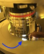
A useful trick before focusing is to do the following:
- Observe the microscope illumination spot on the stage (looking directly at the sample/stage, not through the eyepieces)
- Center the illumination spot on the edge of the sample, so there is a large height difference between the sample edge and the stage.
- Then, while looking through the eyepieces, turn the Coarse knob towards you and observe whether the Edge of the sample becomes more or less blurry. (You can also look at the sample/stage directly to make sure nothing is going to crash.) You should be able to see the hard edge of the sample even when it is very blurry, and focus on the top-surface using this edge.
- Then drive towards the feature on the sample surface you need to image, and the focus should be pretty close (Fine-focus only).
Depth Measurements using focus
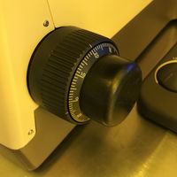
Many microscopes have gradations marked on the fine-focus knob, indicating microns of movement of the sample stage. Using these marks, one can focus on different surfaces and use the gradations to estimate how many microns of vertical separation is present between the two surfaces. Measurement Error stems from your your ability to tell whether a surface is in-focus, often 5-10µm for 5x mag, and more accurate for higher magnifications.
If the microscope has motorized focus, the control software may display the focus height, which can then be used to measure the depth between different focus heights.
Focusing on a sample with no features (Focus Stop)
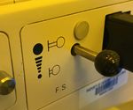
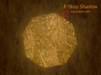
If your sample has no features or dust to focus on, you can still make sure you are focused on the sample surface using an adjustable aperture that projects a shadow on the sample, called a “Focus Stop” (sometimes marked as F.S.). When the edge of this shadow is sharp, the surface is in focus.
Microscope Objectives
Preventing a Crash
Changing objectives is the easiest way to crash into a sample, especially with motorized objective turrets. A few tips can easily prevent this from happening.
ALWAYS begin at low magnification where the working distance between the sample and objective is largest and the depth of focus is also largest.
The microscope objectives on all our microscopes are designed such that the sample is still approximately in focus when an objective is changed. Thus, one should only change objectives when there is some feature that is in focus on the sample. If you don't see anything at all, either because there are no features or because the sample is out of focus, find something to focus on before changing objectives! The “focus stop” iris (above), pieces of dirt or dust are particularly useful for this purpose, and the wafer edges often have such dirt from tweezers etc. The Field Iris / Focus Stop / Shadow for focusing mentioned above would also help.
Working Distance
Working Distance or WD of an objective is the distance (usually in millimeters) from the objective lens to the sample, for the sample to be in focus.
Generally, the lower the magnification, the longer the working distance.
For example, a 5x objective may have a long working distance (distance to sample) of 10mm, while the 100x may be very close at 0.2mm.
Thus it is very important that initial focus is found with a low magnification (and corresponding long working distance). Also the focal depth (range over which sample stays in focus) is wider for low mag, making it much easier to find the focal height, so you should always switch to the lowest mag. before starting to image your sample. (And switch back to lowest mag. when done, out of courtesy for the next user.)
Some objectives may actually have "WD" printed on them. For example, "WD 1.0" means that the sample will be in focus when it is approx. 1.0mm away from the objective. This is very helpful when estimating, by eye, whether you need to move the sample stage up or down to get into focus. If the objective says "WD 0.2" that means it has to be so close that you really should just start at low mag. and work your way up, keeping the sample in focus at each successive magnification!
Digital Imaging & Measurements
Many of our microscopes have cameras and software for image capture.
For our scopes that have AmScope cameras and software installed, please see the following tutorial for making/saving measurements:
Measurements outside the lab
If you know the microscope and objective used for acquiring a photo, you can make calibrated measurements on the photos at your own desktop using the following software:
- AmScope Software - free microscope image analysis software, installed on many of our scopes.
- Measurements and Imaging with Amscope Camera - Quickstart Usage Guide
- AmScope Calibration File containing calibrations for all NanoFab microscopes: Download Here
- Also available on Nanofiles-SFTP / Manuals / Amscope
- FIJI - scientific image analysis software - for stand-alone image analysis after acquiring images.
- The Microscope Measurement Tools plugin has pre-configured calibrations for NanoFab microscopes & SEMs, and allows you to draw length measurements.
- Calibrations in this plugin repository are out of date as of microscope upgrades in 2019.
- There are many other useful plugins, for particle counting, creating animations etc.
- The Microscope Measurement Tools plugin has pre-configured calibrations for NanoFab microscopes & SEMs, and allows you to draw length measurements.
Imaging Modes & Optical Filters
Numerous imaging modes can be enabled or enhanced via optical filters available on the scopes.
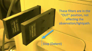
The filters have a detent (you can feel a "click" when they reach this position) so that they can be pulled out to a "stop" where they are not affecting with the lightpath, while remaining in the tool.
Do not pull the filters past the detent, or they may block the light path, and please don't remove them fully from the microscope.
"Yellow" Filter for Photoresist
Uses
- Prevent exposing photoresist
The Yellow/Green filters block Blue and UV light.
These filters will be labelled with:
- "GIF" (green light only) or
- "Y" (yellow)
Neither of the above filters will expose I-line, DUV or EBL photoresists. Light hitting the stage should look yellow or green when inserted.
Adjusting Brightness
Aperture
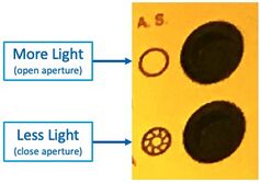
The adjustable Aperture can be used (on Scope #3/#4) to vary the illumination brightness:
ND Filters - "Neutral Density"
- These filters reduce illumination/brightness.
These filters just reduce the incoming brightness, like wearing sunglasses. They do so without altering the color of the light.
You can insert more ND filters to further dim the input light.
ND16 is dimmer than ND8 - put both in for even dimmer illumination.
DIC/Nomarksi Imaging
Uses
- Highlighting particles
- Observing topography/height differences.
- Converts nanometer-level topography/height differences into color.
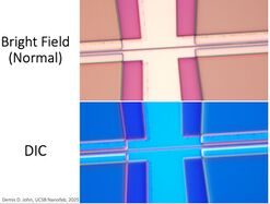
Differential Interference Contrast (aka. "DIC") converts nanometer-level height differences into color differences, operating similarly to a polariscope. This allows the user to observe and identify small/thin residues, height differences or particulates. Photoresist residues are best observed with this method. Very small etch depths (eg. few-nm layers, or unintended etching by O2 plasma) can also be observed.
Many of our scopes have DIC imaging capabilities, although the filters that need to be inserted are arranged differently on each.
DIC Filters Needed
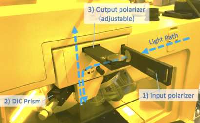
To enable DIC imaging, your scope needs
1) Input light to be polarized (often adjustable)
2) A prism inserted above the microscope objective
3) Output light (towards the observer) to be polarized, with adjustable rotation
The user should rotate the polarization to obtain the best image (eg. with highest contrast).
NOTE: The DIC prism creates a slight double-image when inserted - make sure to pull it out to it's detent for normal imaging!
DIC on Microscopes 3/4
For Microscope #3, all three of these filters may be inserted/removed as indicated:
DIC on FL-Scope
On the Fluoroscope, the rotatable filter wheel sets both the input & output polarizers simultaneously when you set it to "DIC", but you still need to insert/remove the DIC Prism.
DIC on µScope-2
The DIC prisms are located directly on the microscope objectives, and are not intended to be manually inserted/removed. We have left the DIC prisms only on the lower-mag objectives, and removed them from the 100x/150x objectives (where DIC imaging doesn't really work that well), in order to provide better high-mag imaging.
You still have to insert/remove the two polarizers.
The Input polarizer has motorized rotation, controlled by the controller pendant.
Dark Field Imaging

Uses
- Observing particles on flat surfaces
- Observing edges of features
- Estimating particle count vs. size
Enabling Dark Field

Dark Field can be enabled by pulling the BF/DF slider to the "DF" position. "BF" puts it back into standard "Bright Field" mode.
Bright/Dark Field Explanation

The default microscope mode is Bright-Field imaging, where flat reflective surfaces on your sample are "bright" (illuminated). Incoming light hitting a flat surface is reflected straight back through the microscope objective, to reach the eyepieces/camera.
Dark Field imaging instead sends light through the sides of the microscope objective, so incoming light hits the sample at an angle. Light that hits a flat surface thus misses the optical path back to the eyepieces/camera, appearing "dark". Only light that hits curved/non-flat surfaces will be scattered back up through the microscope objectives, producing a bright spot.
Tips for particle estimations using Dark Field
The brightness of the illumination has a huge effect on how many particles will be observed. For example, in DF mode a dim microscope will show fewer particles than a brightly-illuminated microscope. If you are using Dark Field to clean samples or reduce particles on the surface, I recommend the following practices
- Use the same microscope each time - different microscopes have different illumination intensities.
- Raise the illumination brightness to maximum (just to provide a consistent brightness)
- Open the Illumination Aperture to maximum, with this button:
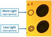
"A.S." Aperture Stop open/close buttons on Microscope #4 - Remove all ND filters, and/or take note of which are inserted. Use these for reducing the brightness if desired.
This page is in-progress, to add:
• Epi/Dia illum.
Written by Demis D. John, 2024-11-25
