Film Stress (Tencor Flexus): Difference between revisions
Jump to navigation
Jump to search
Content deleted Content added
moved to bay 1 |
No edit summary |
||
| (4 intermediate revisions by one other user not shown) | |||
| Line 1: | Line 1: | ||
{{ |
{{tool2|{{PAGENAME}} |
||
|picture=Tencor.jpg |
|picture=Tencor.jpg |
||
|type = Inspection, Test and Characterization |
|type = Inspection, Test and Characterization |
||
|super= Lee Sawyer |
|super= Lee Sawyer |
||
|super2= Mike Silva |
|||
|phone=(805)839-3918x219 |
|phone=(805)839-3918x219 |
||
|location=Bay 1 |
|location=Bay 1 |
||
| Line 15: | Line 16: | ||
=Equipment Specifications= |
=Equipment Specifications= |
||
*Measurement range is 2E7 to 4E7 dyne/cm2 |
|||
*RT to 500°C operation |
|||
*Stress can also be measured as a function of time or temperature. The system has a temperature range from room temperature to 500°C. |
|||
*Measurement results are organized in an easy to read spreadsheet format that can easily be exported to other data handling software such as Excel. |
|||
*Windows 3.xx control and file storing |
*Windows 3.xx control and file storing |
||
*3-D mapping |
*3-D mapping |
||
*4" wafers |
|||
*Laser/Detector Scanning Configuration |
*Laser/Detector Scanning Configuration |
||
*Substrates must be round and films must be reflective. |
|||
*Fixtures are available for 2, 3, 4, 5, and 6" wafers. 8" wafers can be ran as well without a fixture. |
|||
== Documentation == |
|||
* [https://wiki.nanotech.ucsb.edu/w/images/4/4d/Tencor_FLX_SOP_Rev_B.pdf Tencor Flexus Standard Operating Procedure] |
|||
Latest revision as of 18:58, 30 August 2022
| ||||||||||||||||||||||||||||
About
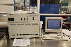
The Flexus instrument is used to measure the stress introduced onto a wafer after thin-film deposition by measuring local curvature of a wafer. The system uses a scanning laser detector configuration to measure the surface position of a wafer across its diameter. With automatic rotational control, a 3-D map can also be obtained. By comparing before and after measurements of the sample, the local stress of the sample can be calculated from the local curvature. The stage can also be heated up to 500°C to measure thermal mismatch of the thin films with the substrate.
Equipment Specifications
- Measurement range is 2E7 to 4E7 dyne/cm2
- Stress can also be measured as a function of time or temperature. The system has a temperature range from room temperature to 500°C.
- Measurement results are organized in an easy to read spreadsheet format that can easily be exported to other data handling software such as Excel.
- Windows 3.xx control and file storing
- 3-D mapping
- Laser/Detector Scanning Configuration
- Substrates must be round and films must be reflective.
- Fixtures are available for 2, 3, 4, 5, and 6" wafers. 8" wafers can be ran as well without a fixture.
