ASML Stepper 3 Dicing Guide Programming
How to program the ASML DUV Stepper #3 to place dicing guides in between die.
- Determine a lithography step in the fabrication process during which the addition of dicing guides (crosses) on positive PR would be acceptable and visible during dicing.
- When programming the job, add an new Image in
Wafer Layout > Image Definitionfor the DicingGuides image, as so:- Reticle ID: "UCSB-OPC1" (hyphenated)
- Image Size (Wafer): X = 0.90000; Y = 0.90000 mm
- Image Shift (Wafer): X = -6.750000; Y= -9.450000 mm
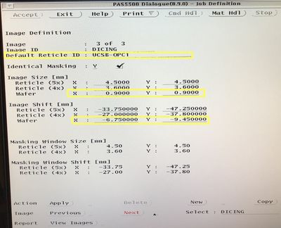
ASML Programming: Image Definition Screen 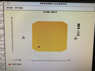
Image Definition: Location on Reticle


- Under
Wafer Layout > Image Distribution, add anImage-to-Cell Shiftof half the die X/Y size, andApplyto all die, to place the marks at the corner of every die.- The software will only let you place the die at the upper-right (+X,+Y) corner. To include the lower-left corners, you will need to make sure you enabled the
Wafer Layout > Cell Structure > Die Definition > # of Dies & Minimum per Celloptions so it'll shoot partial die. - Make sure they don't expose over any of your other alignment marks!
- The software will only let you place the die at the upper-right (+X,+Y) corner. To include the lower-left corners, you will need to make sure you enabled the
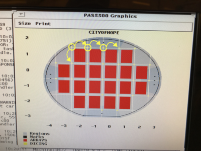
Image Distribution: Example dicing mark locations, using Image-to-Cell Shift to place die at corners.
