Thermal Evaporator 1: Difference between revisions
No edit summary |
m added missing { |
||
| (2 intermediate revisions by one other user not shown) | |||
| Line 1: | Line 1: | ||
{{tool|{{PAGENAME}} |
|||
=[[Thermal Evaporator #1)]]= |
|||
|picture=Thermal1.jpg |
|||
|type = Vacuum Deposition |
|||
|super= Mike Silva |
|||
|phone=(805)839-3918 |
|||
|location=Bay 3 |
|||
|email=silva@ece.ucsb.edu |
|||
|description = NRC 3117 Three Source Thermal Evaporator |
|||
|manufacturer = ?? |
|||
|materials = |
|||
|toolid=11 |
|||
}} |
|||
= About = |
|||
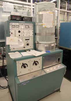
This system is the primary thermal evaporator (tungsten strip or wire resistance heater source boats) in the cleanroom. It complements and augments offered by the Sharon e-beam system in that p-type contacts for III-V compounds such as Zn may only be done here, but it allows for easier access and depositions without the risk of radiation damage for many of the same materials as the e-beam. The system has been upgraded over the years from its original diffusion pump design to now include a cryopump and custom-built electronics for turn-key pumpdown and venting operations. Typically source materials are melted in "dimpled" flat tungsten boats. These include: Al, Ag, Au, Au/Ge, Au/Pd, Au/Zn, Cr, Mn, Ni, SiO and Zn. Cr is evaporated (sublimed) from a pre-coated rod and SiO from a special baffle heater, both available from R.D Mathis Co. Evaporation rates are manually controlled by varying the output voltage of a variac which feed various transformer taps (and feedthroughs) allowing for currents up to 200 amps. Although the unit heater boat selector can theoretically accommodate up to four units, present fixturing only allows for three, which are heated sequentially. Rates are monitored with a standard 6 mHz crystal oscillator. Samples typically are piece parts or quarters of 2 inch wafers, and are clipped onto a removable metal plate which sits at approximate 12 inches from the sources. At present 2 inch wafers would be the maximum sample size for 100% coverage. The substrate rotation fixture from the Sharon system can also be used. Substrate heating is possible with user supplied heater assemblies. Deposition cycling time from pumpdown to deposition to system venting is two hours, the same as the e-beam systems. |
|||
=Detailed Specifications= |
|||
*Standard 18" bell jar pumped by 8" Varian cryopump (HV8) driven by Ebara 2.1 compressor |
|||
*Low E-7 Torr ultimate pressure |
|||
*Rate Monitor: Maxtek TM-300 |
|||
*Typical material rates: Al - 1 A/s @ 85 amps |
|||
**Au - 5 A/s @ 122 amps |
|||
**Cr - 2 A/s @ 85 amps |
|||
**Zn - 4.5 A/s @ 50 amps |
|||
= Materials Table = |
|||
For the materials tables, please visit the [[Thermal_Evaporation_Recipes#Materials_Table_(Thermal Evaporator #1)|Thermal Evaporation Recipe Page]]. |
|||
=Documentation= |
|||
*{{file|ThermalEvapInstruction.pdf|Standard Operation Instructions}} |
|||
Latest revision as of 00:31, 13 October 2017
| |||||||||||||||||||||
About
This system is the primary thermal evaporator (tungsten strip or wire resistance heater source boats) in the cleanroom. It complements and augments offered by the Sharon e-beam system in that p-type contacts for III-V compounds such as Zn may only be done here, but it allows for easier access and depositions without the risk of radiation damage for many of the same materials as the e-beam. The system has been upgraded over the years from its original diffusion pump design to now include a cryopump and custom-built electronics for turn-key pumpdown and venting operations. Typically source materials are melted in "dimpled" flat tungsten boats. These include: Al, Ag, Au, Au/Ge, Au/Pd, Au/Zn, Cr, Mn, Ni, SiO and Zn. Cr is evaporated (sublimed) from a pre-coated rod and SiO from a special baffle heater, both available from R.D Mathis Co. Evaporation rates are manually controlled by varying the output voltage of a variac which feed various transformer taps (and feedthroughs) allowing for currents up to 200 amps. Although the unit heater boat selector can theoretically accommodate up to four units, present fixturing only allows for three, which are heated sequentially. Rates are monitored with a standard 6 mHz crystal oscillator. Samples typically are piece parts or quarters of 2 inch wafers, and are clipped onto a removable metal plate which sits at approximate 12 inches from the sources. At present 2 inch wafers would be the maximum sample size for 100% coverage. The substrate rotation fixture from the Sharon system can also be used. Substrate heating is possible with user supplied heater assemblies. Deposition cycling time from pumpdown to deposition to system venting is two hours, the same as the e-beam systems.
Detailed Specifications
- Standard 18" bell jar pumped by 8" Varian cryopump (HV8) driven by Ebara 2.1 compressor
- Low E-7 Torr ultimate pressure
- Rate Monitor: Maxtek TM-300
- Typical material rates: Al - 1 A/s @ 85 amps
- Au - 5 A/s @ 122 amps
- Cr - 2 A/s @ 85 amps
- Zn - 4.5 A/s @ 50 amps
Materials Table
For the materials tables, please visit the Thermal Evaporation Recipe Page.
