Stepper 3 (ASML DUV): Difference between revisions
→Operating Procedures: link to error & calibration procedure |
m →Operating Procedures: moved Error recovery to "troubleshootin" section |
||
| Line 44: | Line 44: | ||
=Operating Procedures= |
=Operating Procedures= |
||
* [[ASML Stepper 3 Standard Operating Procedure|Standard Operating Procedure]] |
* [[ASML Stepper 3 Standard Operating Procedure|Standard Operating Procedure]] |
||
| ⚫ | |||
* [[media:ASML Job Set-Up Guide v2.pdf|Job Programming - Full]] |
* [[media:ASML Job Set-Up Guide v2.pdf|Job Programming - Full]] |
||
| Line 51: | Line 50: | ||
=== Troubleshooting and Recovery === |
=== Troubleshooting and Recovery === |
||
| ⚫ | |||
** ''Common errors, General error recovery, and system calibration check'' |
|||
* [[ASML 5500: Recovering from an Error]] |
* [[ASML 5500: Recovering from an Error]] |
||
** ''How to abort the job and recover your wafer.'' |
** ''How to abort the job and recover your wafer.'' |
||
Revision as of 21:19, 17 July 2018
|
About
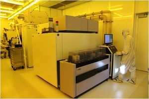
The ASML 5500 stepper is a 248nm DUV stepper for imaging dense features down to below 200nm and isolated line structures down to below 150nm. Overlay accuracy is better than 30nm.
The system is configured for 4” wafers and, with staff support, mounted pieces down to 14mm in size can be exposed using a 4” wafer as a carrier. The system is designed for high throughput, so shooting multiple 4" wafers is extremely fast. Additionally, exposure jobs are highly programmable, allowing for very flexible exposures of multiple aligned patterns from multiple masks in a single session, allowing for process optimization of large vs. small features in a single lithography.
The full field useable exposure area is limited to the intersection of a 31mm diameter circle and a rectangle of dimensions 22mm x 27mm. See the Mask Making Guidelines page for more info on exposure field sizes and how to order your mask plates.
Resists Used (see PhotoLith. Recipes for processing info):
- UV210-0.3 - Positive: 300nm nominal thickness
- UV6-0.8 - Positive: 800nm nominal thickness
- UV26-2.5 - Positive: 2.5um nominal thickness
- UVN2300-0.5 - Negative: 500nm nominal thickness
- AR2/DUV42P-6/DS-K101: Anti-Reflective Coatings
- PMGI: Underlayer
AZ300MIF Developer for all processes
Process Information
- Process Page
- Alignment Accuracy: < 50 nm
- Minimum Feature Size: ≤150 nm isolated lines, ≤200 nm dense patterns
- Maximum Wafer Bow: approx. 100 µm. (4-inch diam.).
- Above this and the job may fail or lose the wafer inside the machine due to wafer vacuum error.
Service Provider
Operating Procedures
Troubleshooting and Recovery
- Error Recovery, Troubleshooting and Calibration
- Common errors, General error recovery, and system calibration check
- ASML 5500: Recovering from an Error
- How to abort the job and recover your wafer.
- ASML 5500: Recovering from a Typo in Reticle ID
- If you ran a job and got "Reticle Not Present" due to a typo in your job/layer/image's reticle ID.
- ASML 5500: Choose Marks for Prealignment
- If your job aborted with "Alignment failure" on the P-Chuck, because it couldn't find the alignment marks, this is how to edit your job to use different alignment marks.
